recommend News
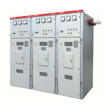
KGN-12 type box-type fixed metal enclosed switchgear
KGN-12 type box-type fixed metal-enclosed switchgear (referred to as switch cabinet) is suitable for 3-12KV three-phase AC 50Hz, single bus or single bus with bypass, and double bus systems for receiving and distributing electrical energy. It can meet the usage requirements of various types of power plants, substations, and industrial enterprises.
Key words:
People's Power
Transformer
Substation
Power equipment
Classification:
Product Description
1. Purpose and Scope of Application
KGN-12 type box-type fixed metal-enclosed switchgear (referred to as switch cabinet) is suitable for 3-12KV three-phase AC 50Hz, single bus or single bus with bypass, and double bus systems for receiving and distributing electrical energy. It can meet the usage requirements of various types of power plants, substations, and industrial enterprises.
This product complies with the national standard GB3906-2006 "3-35kV AC Metal-Enclosed Switchgear" and the international standard IEC298. This product has a reasonable structure, high safety reliability, and is easy to operate and maintain; it has the "five prevention" functions, and the protection level reaches IP2X.
The main switch of this product uses ZN28A-12 type vacuum circuit breaker and VS1-12 type vacuum circuit breaker, and the operating mechanism can be equipped with CT19B spring operating mechanism. The isolating switch uses GN30-10 rotary isolating switch.
2. Normal Operating Environmental Conditions
(1) Ambient air temperature: upper limit +40℃; lower limit -25℃;
(2) Altitude: not exceeding 2000m; plateau full working condition products not exceeding 3000m;
(3) Relative humidity: daily average not greater than 95%; monthly average not greater than 90%, short-term condensation allowed;
(4) Seismic intensity not exceeding 8 degrees;
(5) No fire, explosion hazards, severe pollution, chemical corrosion, or severe vibration conditions.
3. Model Meaning
4. Technical Data
4.1 Technical data of the switch cabinet see Table 1
| Item Number | Project | Unit | Technical Parameters | ||||
| 1 | Rated Voltage | kV | 3, 6, 10 | ||||
| 2 | Maximum Working Voltage | kV | 3.5, 6.9, 12 | ||||
| 3 | Rated Current | A | 630~2500 | ||||
| 4 | Maximum Working Current | A | 630 | 1000 | 1000 | 2000 | 2500 |
| 5 | Rated Breaking Current | kA | 20 | 31.5 | 40 | ||
| 6 | Rated Thermal Stability Current | kA | 20 | 31.5 | 40 | ||
| 7 | Rated Dynamic Stability Current | kA | 50 | 80 | 100 | ||
| 8 | Rated Closing Current | kA | 50 | 80 | 100 | ||
| 9 | Thermal Stability Time | s | 4 | ||||
| 10 | Protection Level | IP2X | |||||
| 11 | Bus System | Single Bus | |||||
| 12 | Operating Mode | Spring Energy Storage Type | |||||
| 13 | Dimensions (Width × Depth × Height) | mm | 1200×1200×2650 | ||||
| 14 | Weight | kg | |||||
4.4, The adjustment parameters of the vacuum circuit breaker are shown in Table 5
| Serial number | Name | Single unit | Data |
| 1 | Contact opening distance | mm | 12±1 |
| 2 | Contact stroke | 4±1 | |
| 3 | Oil buffer stroke | 100-3 | |
| 4 | Center distance between phases | mm | 250 (210) |
| 5 | Three-phase disconnection synchronization | ms | ≤2 |
| 6 | Closing contact bounce time | ≤5 | |
| 7 | Closing contact pressure | N | 2000±200 |
| 8 | Average disconnection speed (before contact oil buffer) | m/s | 1±0.3 |
| 9 | Average closing speed | 0.55±0.15 | |
| 10 | Resistance of each conductive circuit | μΩ | ≤40 |
| 11 | Cumulative allowable wear thickness of moving and static contacts | mm | 3 |
4.5, The technical parameters of the isolating switch are shown in Table 6 and Table 7
| Name | GN30-10/400 | GN30-10/630 | GN30-10/1000 | ||
| GN30-10D/400 | GN30-10D/630 | GN30-10D/1000 | |||
| Rated Voltage | kV | 10 | |||
| Maximum Working Voltage | kV | 12 | |||
| Rated Current | A | 400 | 630 | 1000 | |
| 4s rated thermal stability current | kA | 12.5 | 20 | 31.5 | |
| Rated Dynamic Stability Current | kA | 31.5 | 50 | 80 | |
| Rated insulation level | 1.2/50μs lightning impulse withstand voltage | kV | 75 | ||
| 1min power frequency withstand voltage | kV | 42 | |||
Related Products
Product Inquiry


